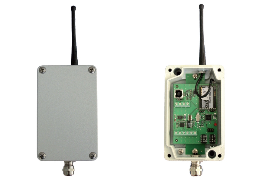
INTERFACE from RS232 / RS485 / USB to RF.
Selecting the desired configuration (MULTI or SINGLE) by hardware jumper.
In multi interface allows up to 15 transmitters weighing TRF, the same radio channel.
RF channel selection, baud rate and communication address via DIP-SWITCH.
Power supplì 4.5Vdc XX 15Vdc or from USB.
PC application for configuration.
![]() Click to enlarge image
Click to enlarge image

| Power supply | 4.5 Vdc - 15 Vdc ( 50 mA) | |
| Operating temperature | -10 / +50 °C (14 / 122 °F) Humidity Maximum 85% non-condensing | |
| Storage temperature | -20 / +60°C (-4 / +140°F) | |
| Overall dimensions | 5.0 x 3.1 x 1.6 in (l x h x d) excluding antenna and connector | |
| Case material | Die cast aluminum | |
| Protection level | IP 65 | |
| Connections | 5.08 pitch screw terminal blocks with cable entry / 5-pin connector | |
| Rs232 | Comunication parameters: 9600/19200/38400,N,8,1. Signal management: Txd, Rxd, Sgnd. | |
| Rs422 / Rs485 | Comunication parameters: 9600/19200/38400,N,8,1. | |
| USB | Communication parameters: 9600/19200/38400, N, 8, 1. Signals managed: Txd, Rxd, Sgnd | |
| Frequency | 866-868 MHz | |
| Num. RF Channels | 7 selectable by DIP switch | |
| Num. Network address | 15 selectable by DIP switch | |
| Average radius of coverage | 50 m (165 feet) | |
| Conforms to standards | EN 300 220, EN 301 489, EN 60950, EN61000-6-2, EN61000-6-3, EN61010-1 | |
| Type | RRF Connections |
| Length | 15 m |
| 1 | +5 Vdc |
| 2 | GND |
| 3 | RS232 Tx |
| 4 | RS232 Rx |
| 5 | RS422/485 + |
| 6 | RS422/485 - |
General precautions to be followed in the installation and assembly of load cells: