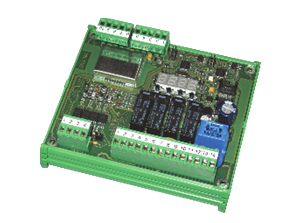
LOAD LIMITER for load cells.
Load cells power supply protected against short-circuit.
![]() Click to enlarge image
Click to enlarge image

| Power supply | 10 - 30 VDC, protected against polarity inversion. Protection with resettable fuse | |
| Max power consumption | 6 W | |
| Isolation | Class III (only circuit board) | |
| Operating temperature | -10 / +50 °C (14 / 122 °F) Humidity Maximum 85% non-condensing | |
| Display | 4-digit numeric red LED with 7 segments (h 7 mm) | |
| Led | 4 LED indicating relay outputs | |
| Load cell input features | Maximum 4 350 Ω load cells in parallel. Load cells power supply protected against short-circuit | |
| Linearity | < 0.01% of full scale | |
| Temperature deviation | < 0.002% of full scale/C° | |
| Internal resolution | 24 bit | |
| Weight resolution | Up to 10,000 divisions of load | |
| Measuring range | From -3.9 mV/V to +3.9 mV/V | |
| Digital filter | Selectable 0.25 Hz – 3 Hz | |
| Zero / FS Calibration | Automatic (theoretical) or executable through buttons | |
| Serial port | 2 RS232 programming module | |
| Max. cable length | 15 m | |
| Serial protocols | CANOpen port (optional) Data transmission and card programming | |
| Conforms to standards | Compliance to EMC norms: EN61000-6-2, EN61000-6-3, Compliance electric safety: EN 61010-1, EN13849-1 | |
General precautions to be followed in the installation and assembly of load cells: